Subchapter 3.7
Selection and design of monitoring systems
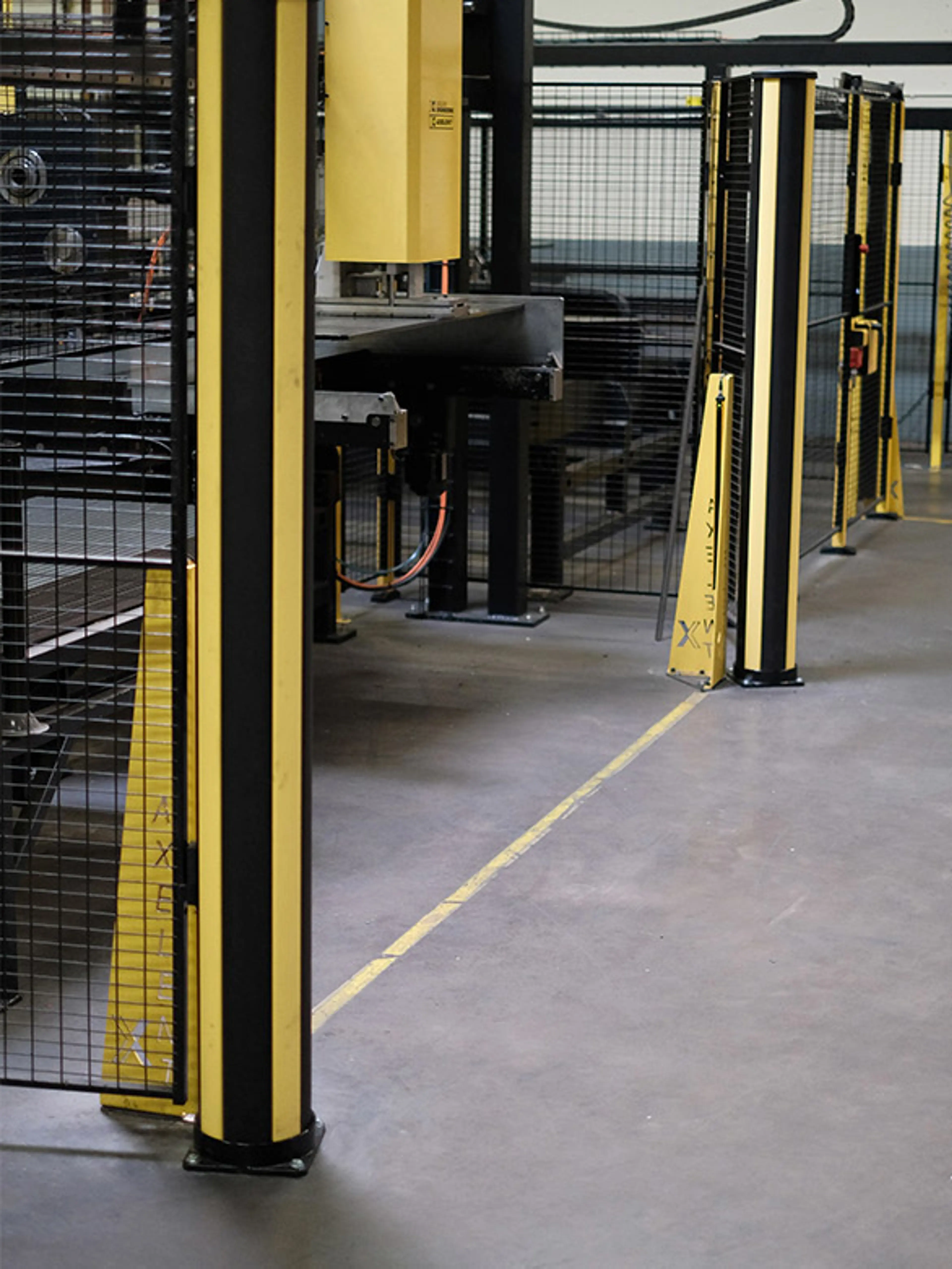
Monitoring devices play a crucial role in machine safety, but they have limitations. These devices cannot protect against hazards such as ejected parts, hot surfaces, liquids, or other emissions. In the following section we will guide you through the different alternatives.
Alternatives to movable guards
There are many alternatives to the movable guard with interlocking , including monitoring systems. These options do however come with disadvantages that we will discuss.
The following monitoring systems can include:
- Light barriers, light curtains, range scanners
- Contact-sensitive mats
- Trip bars and bumpers
These monitoring systems serve two purposes:
- To monitor access of people and objects into the hazard zone.
- To replace physical guards to allow for easier access, save space or reduce operating time.
However, to achieve the second purpose, these systems come with a significant limitation.
- Ejection of parts
- Spraying of hazardous and/or pressurised liquids
- Hot or very cold parts close by
- Hazardous dust, fog or fumes generated
If your application involves any of these hazards, do not rely solely on monitoring devices as your safety measure.
Sensitive protective devices tend to blur the boundary between the safe area and the hazard zone. People may be unaware of the risk involved or may get used to entering a hazard zone without giving much thought to it.
Often it is not clear to operators when and how the safety device is to respond and what the safety function involves. This may lead to hazardous behaviour. With a fence and guard-locked door on the other hand, entering a hazard zone always is a conscious, wilful action.
Alternative 1
Light barriers, light curtains, range scanners
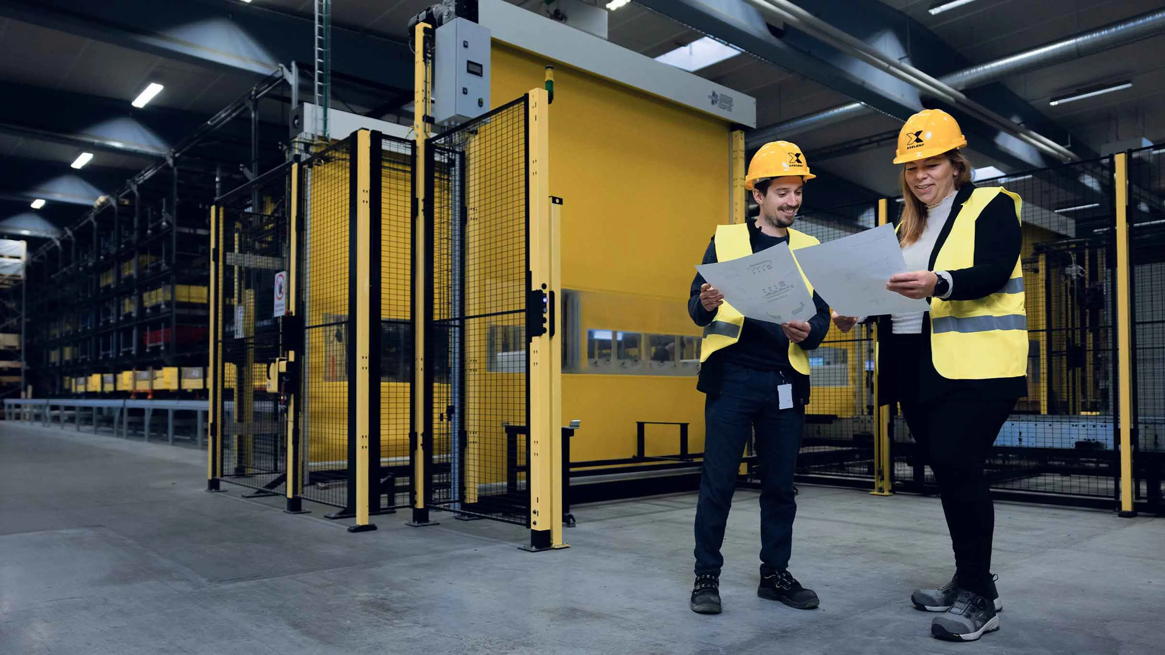
To protect a person from contacting hazardous moving parts, devices like light barriers, light curtains, or laser scanners must detect the person and stop the machine before they reach the hazard zone.
One key limitation of these devices, which is sometimes overlooked, is that they monitor only a single plane, whether it is vertical, horizontal, or at a specific angle. They cannot detect anything outside this selected plane, known as the protective field.
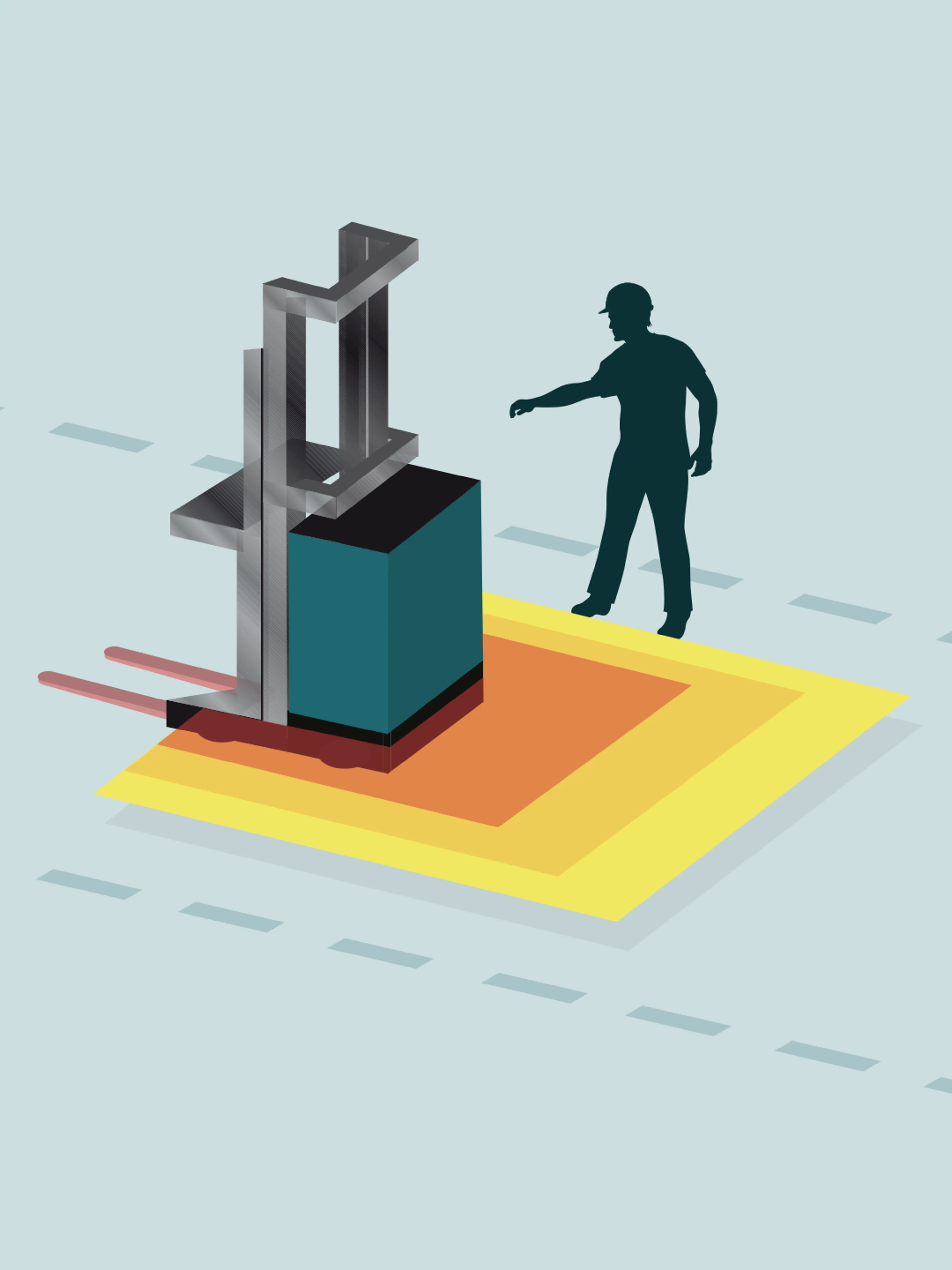
To illustrate, imagine a range scanner installed on a driverless industrial truck. The scanner is designed to detect people in the truck’s path and stop the vehicle if someone gets too close. Normally, you would install the scanner at about 200 mm from the floor for it to detect people standing or walking in the way.
However, it will not detect someone standing next to the truck’s path and stretching out their arm above the detection plane. Since the arm is positioned far above the detection plane, which is set at 200 mm from the floor, the truck could hit the arm and severely injure it.
Key considerations for correct design
To ensure correct design of a light curtain or range scanner application, you need to consider these three questions:
Importance of accurate calculations
Accurate calculations are essential for proper design. Unfortunately, installation locations are sometimes chosen based on guesswork, which can be very dangerous.
Correct calculations should always be made according to the (EN) ISO 13855* standard, which also specifies typical motion and approach speeds for individuals.
These examples highlight the need for caution, especially when light curtains are installed close to the danger zone. If the distance appears to be less than 300 mm, it is likely unsafe, as the stopping time would only be about 0.15 seconds. Remember, a monitoring device is a safety measure, not a gamble. You must calculate, test, and document your findings to ensure it works as intended.
* ISO 13855 is referenced by ANSI B11.0 and B11.19 for the USA and CSA Z432 for Canada. Note, however, that the formulas for safety distance calculations in these standards are slightly different from what is given in (EN) ISO 13855. The standards for safety of driverless automatic industrial vehicles are ISO 3691-4 and ANSI/ITSF B56.5-2024 for the USA.
Alternative 2
Contact sensitive mats
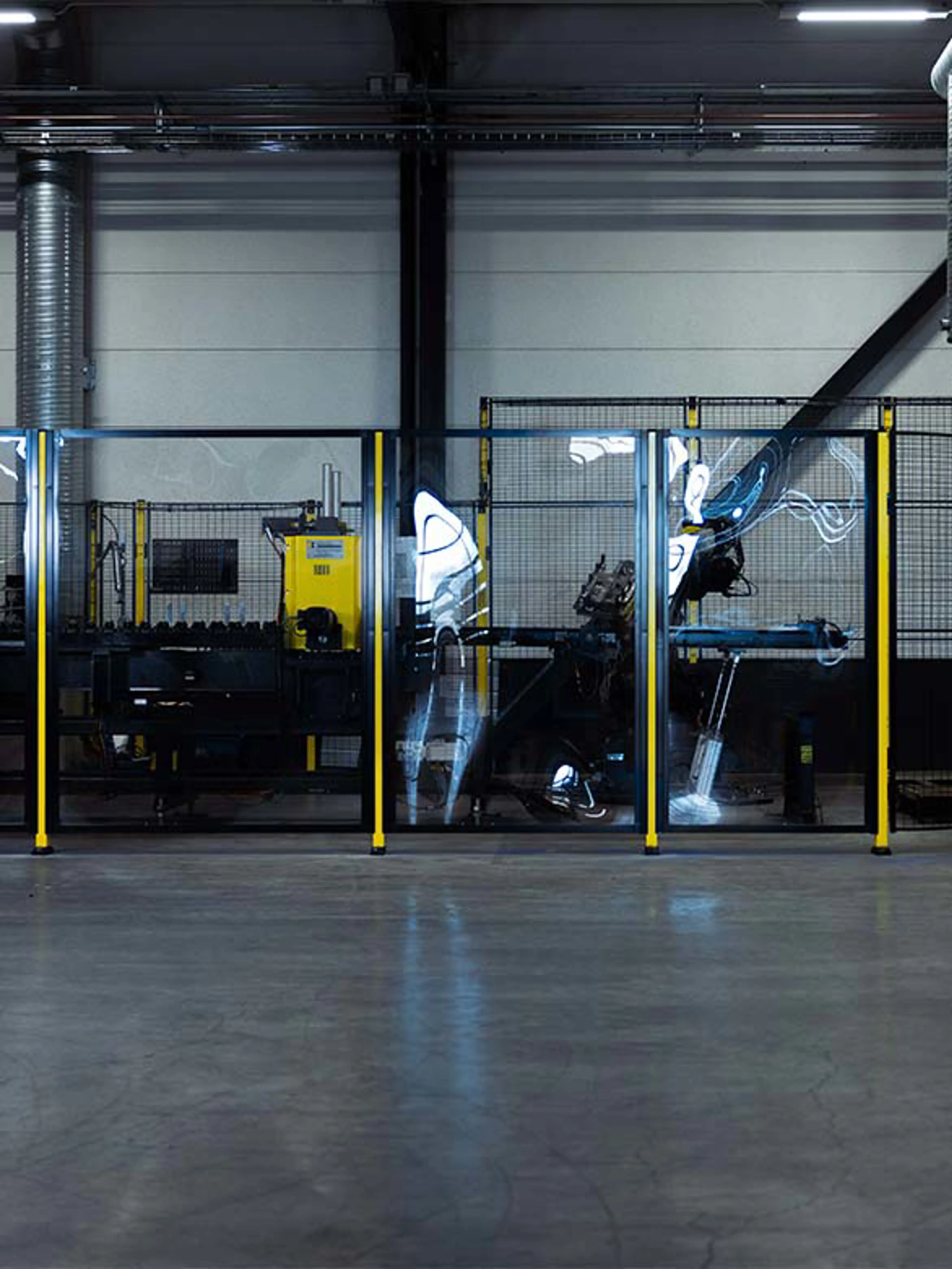
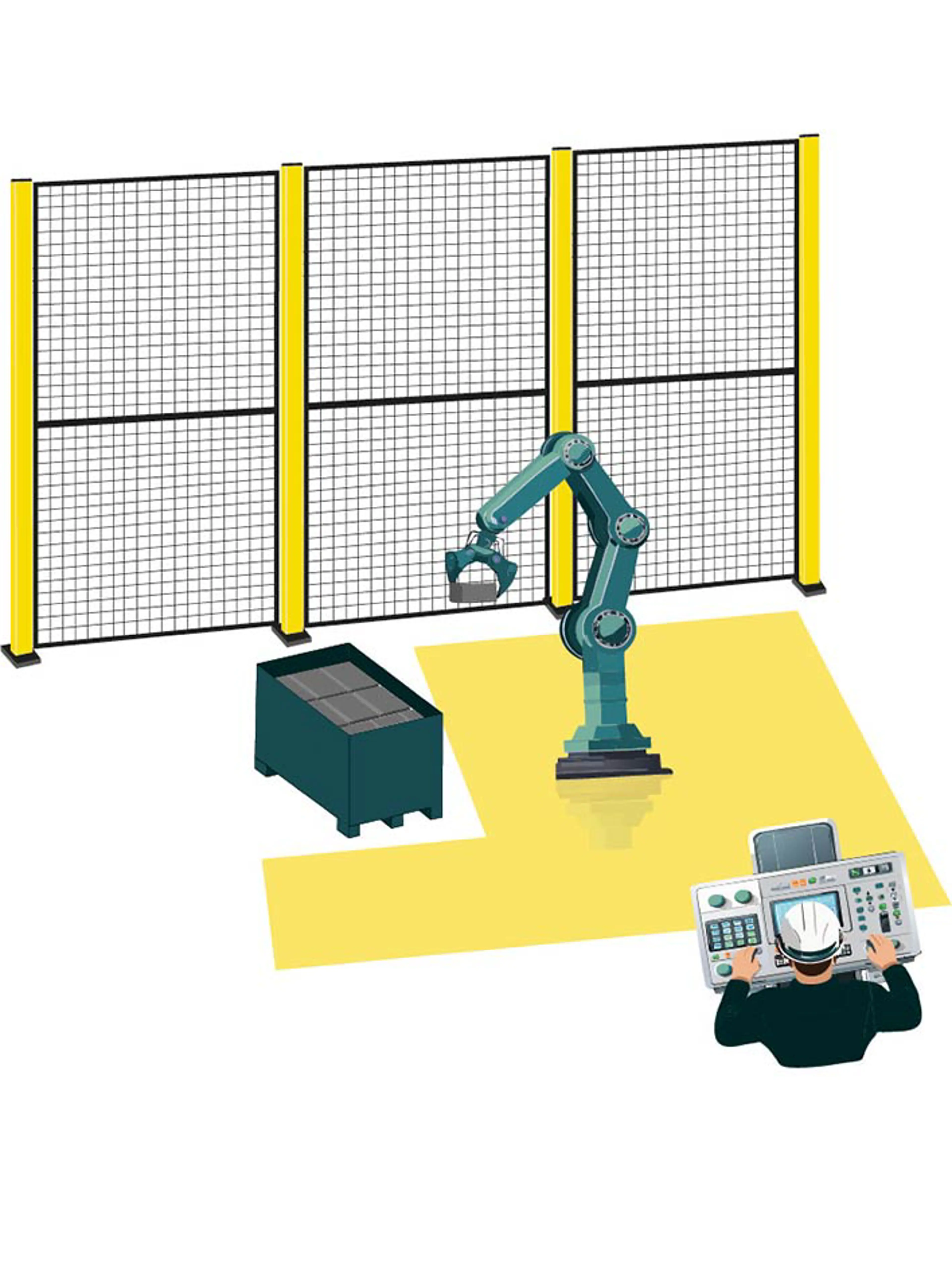
Contact-sensitive mats are a good alternative to light curtains and laser scanners as they are not affected by dust, fog, smoke, dirt, or stray light—factors that can interfere with optoelectronic sensing equipment. Using a contact sensitive mat ensures that operations cease when a person steps on the mat and enters the hazard zone.
When implementing these mats, the distance to the hazard zone is crucial. The time required to stop the hazard must be shorter than the time it takes for someone to step on the mat and reach the hazard zone. This requires careful calculations, and compliance with (EN) ISO 13855 is required.
Thorough testing is essential to ensure that the mat is properly positioned to prevent anyone from "overstepping" it—meaning that it must not be possible for a person to stand on a frame or other machine part on either side of the mat with outstretched legs. Ensuring the hazard has stopped by the time a person reaches the hazard zone is critical for safety and compliance.
Believe it or not, operators may attempt to bypass safety measures, so it's important to account for this in your design.
Alternative 3
Trip bars and bumpers
Trip bars and bumpers detect moving machine parts and cease the movement when they come in contact with a human body, avoiding potential injuries.
There are close limits to such applications:
- Motion speed must be slow (usually less than 250 mm/s), because the impact could otherwise already injure the person or (worse) knock him/ her over.
- The energy of the impact must not exceed 150 N and 10 J.
- The time/path needed to stop must be short.
If these factors are not adhered to there is still a risk of injury since the moving part may not stop before knocking over, crushing or shearing the person.
